


CIP Safety: Safety Networking for Today and Beyond
At a Glance
Communication networks have changed the look of today’s automation systems by distributing processing, sensors and actuators to where they are required. CIP Safety™ provides the same benefits to safety systems. CIP Safety extends the industry standard CIP™ base services by adding CIP Safety distinctive services to transport data for CIP based networks such as EtherNet/IP™ with high integrity.
This paper presents this scalable, network independent approach to safety networking, where the safety services are described in a well-defined layer, allowing the underlying network services to be changed. This approach enables the seamless routing of safety data, allowing the user to create end to end safety chains across multiple links.
Introduction
The same motivations that originally moved communication networks into the industrial environment — greater distances, increased flexibility, reduced cost, and improved maintainability — are also driving the development of industrial safety networks. On top of these incentives, end users also recognize the limitations of traditional hardwired safety solutions as hardwired systems are difficult to develop and maintain for all but the most basic applications. For example, hardwired safety systems employ relays, which are interconnected to provide a safety function. Furthermore, these systems place significant restrictions on the distance between devices. As safety system developers progressed beyond basic E-stop functions, they found themselves forced to fall back to hardwired logic techniques, which have been out of widespread use for control functions since the 1970s. Even when they were successful in developing a significantly sized safety system, these were often costly and difficult to maintain.
Because of these issues and a growing need for process data and flexibility, it is desirable to provide safety services on standard communication networks. The development of CIP Safety by ODVA for use on EtherNet/IP and other networks is one such example. The key to these developments was not to create a network that couldn’t fail, but to create a system in which failures in the network would cause safety devices to go to a known safe state. If users know to which state the system would go, they can make their application safe, yet this means that significantly more checking and redundant coding information would be required. Fortunately, communication networks have become pervasive in automated systems, and electronics capable of advanced diagnostics are widely available.
The foundation of functional safety is the well-established standard IEC 61508 standard. Following the guidance of that standard, additional safety standards specific to industries, products, and technologies have been developed, such as IEC 62061, ISO 13849-1, and IEC 61784-3.
To avoid the complexity and maintenance of designing a dedicated safety-rated network, IEC 61508 and IEC 61784-3 emphasize another option called “the black channel”. The black channel assumes that network is completely unreliable, so diagnostics must exist outside of the network infrastructure. This concept stipulates that if a safety communication protocol has enough error detection built into the protocol, it can be transmitted independently across different network types without degrading the integrity of the safety data. This can include traversing multiple network links and network segmentation techniques.
Building a safety communication protocol with the black channel principle can be problematic if the corresponding standard communication protocol is heavily dependent on non-standard network hardware. Fortunately, CIP Safety is based on the Common Industrial Protocol (CIP), which allows network independent routing of data. These base services were extended to allow high integrity safety services by the addition of CIP Safety distinctive network services. This paper presents a solution for a scalable, routable, network-independent safety layer, thus removing the requirement for dedicated safety gateways. Since all safety devices execute the same protocol, independent of which media on which they reside, the user approach is consistent and independent of media or network used.
CIP Safety: Safety Services Built on the Common Industrial Protocol
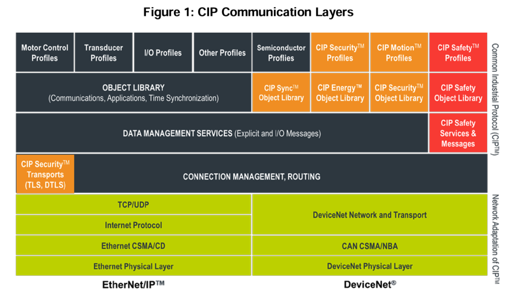
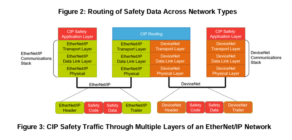
Because the safety application layer extensions do not rely on the integrity of the underlying standard CIP services and datalink layers, single channel (non-redundant) hardware can be used for the datalink communication interface. This same partitioning of functionality allows standard routers to be used to route safety data across networks as long as the underlying safety data is not modified, as shown in Figure 2, and between different layers of complex networks, as shown in Figure 3. The routing of safety messages is possible because the end device is responsible for confirming the integrity of the data. If an error occurs in the transmission of data or in the intermediate router, the end device will detect the failure and take an appropriate action.
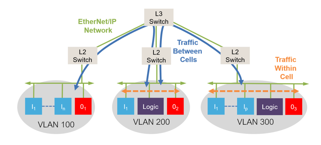
Only the safety data that is needed is routed to the required cell, which reduces the individual bandwidth requirements. The combination of fast responding local safety cells and the inter-cell routing of safety data allows users to create significantly larger and more complex safety applications with fast response times.
Implementing Safety
The CIP Safety application layer is specified using a safety validator object. This object is responsible for managing the CIP Safety connections and serves as the interface between the safety application objects and the link layer connections, as shown in Figure 4. The Safety Validator confirms the integrity of the safety data transfers.
Figure 4: Relationship of Safety Validators Typical of an Output Device [Note: SP = safety producer, P = producer, C = consumer, SC = safety consumer]
![Figure 4: Relationship of Safety Validators Typical of an Output Device [Note: SP = safety producer, P = producer, C = consumer, SC = safety consumer]](https://www.odva.org/wp-content/uploads/2026/07/Pub110_Figure-4_Figure-4_Relationship-of-Safety-Validators-1024x454.png)
- The producing safety application uses an instance of a client validator to produce safety data and confirm time coordination.
- The client uses a link data producer to transmit the data and a link consumer to receive the time coordination messages.
- The consuming safety application uses a server validator to receive and check data.
- The server uses a link consumer to receive data and a link producer to transmit time coordination messages.
The link producers and consumers have no knowledge of the safety packet and fulfill no safety function. The responsibility for high-integrity transfer and checking of safety data lies within the Safety Validators.
Safety Validators Help Ensure Integrity
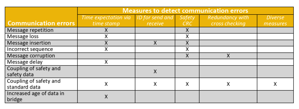
CIP Safety does not prevent communication errors from occurring, but it helps ensure transmission integrity by detecting errors and allowing devices to take appropriate actions. The Safety Validator is responsible for detecting these communication errors. The nine communication errors, which must be detected, are shown in Table 1 along with the five measures CIP Safety uses to detect these errors.
Table 1: Error Detection Measures
Time Expectation via Time Stamp
All CIP Safety data is produced with a time stamp, which allows safety consumers to determine the age of the produced data. This detection measure is superior to more conventional reception timers and watchdog timers. Reception timers can tell how much time has elapsed since a message was last received, but they do not convey any information about the actual age of the data. A time stamp allows transmission, media access/arbitration, queuing, retry and routing delays to be detected.
Time is coordinated between producers and consumers using ping requests and ping responses, as shown in Figure 5. After a connection is established, the producer will produce a ping request, which causes the consumer to respond with its consumer time. The producer will note the time difference between the ping production and the ping response and store this as an offset value to its producer time for all subsequent data transmissions. This value is transmitted as the time stamp. When the consumer receives a data message, it subtracts its internal clock from the time stamp to determine the data age. If the data age is less than the maximum age allowed, the data is applied. If the age of the data is beyond the age limit, the data is discarded, so that only recent data is used. Typically, configurable settings allow the user to determine how many missed, late, or lost packets should be allowed before going to the safe state. Once in the safe state, the device application is notified so that the connection safe state can be appropriately reflected.
Figure 5: Time Expectation, Ping and Offset
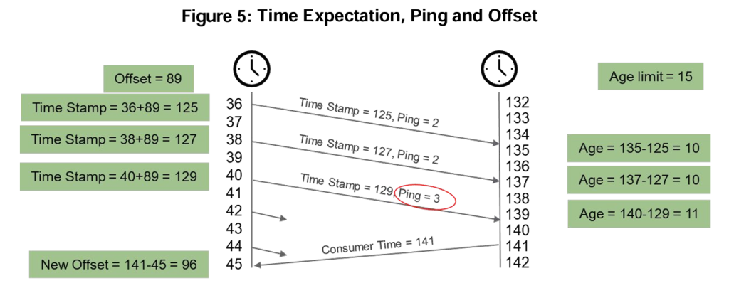
The ping request and response sequence is repeated periodically to correct for any drift in producer or consumer crystal drift.
Time Stamps Provide Availability
A safety network is only useful for production if it is available. False trips reduce availability and limit the useful applications of a network. CIP Safety provides tolerance to minor disturbances by allowing retransmissions. As long as the retransmission is received before the expected time interval expires, the network connection can continue to operate.
Production IDentifier (PID)
A Production IDentifier is encoded in each safety packet produced to confirm that each received message arrives at the correct consumer. The PID is derived from an electronic key, the device serial number and the CIP connection serial number. Any device inadvertently receiving a message with the incorrect PID will go to a safe state. Any device that does not receive a message within the expected time interval with the correct PID will also go to a safe state. This measure confirms that messages are routed correctly in multilink applications.
Safety CRC (Cyclic Redundancy Code)
All safety transfers on CIP Safety use Safety Cyclic Redundancy Codes (CRCs) to confirm the integrity of the transfer of information. The Safety CRCs serve as the primary reassurance to detect possible corruption of the transmitted data. They provide detection up to a Hamming distance of 4 for each data transfer section, though the overall Hamming distance coverage is greater for the complete transfer due to the redundancy of the protocol. The Safety CRCs are generated in the safety producers and checked in the safety consumers. Intermediate routing devices do not examine the Safety CRCs. Thus, by employing end-to-end Safety CRCs, the individual datalink CRCs are not part of the safety function. This eliminates the certification requirements for intermediate devices and helps to ensure that the safety protocol is independent of the network technology and it is core to the black channel principle. The Safety CRC also provides a strong protection mechanism which allows underlying datalink errors such as bit stuffing or fragmentation errors to be detected.
The individual link CRCs are not relied on for safety, but they are still enabled. This provides an additional level of protection and noise immunity by allowing data retransmission for transient errors at the local link.
Redundancy and Cross Check
Data and CRC redundancy with cross checking provides an additional measure of protection by detecting possible corruption of transmitted data, which effectively increases the Hamming distance for improved error detection. These measures allow long safety data packets, up to 250 bytes, to be sent with high integrity. For short packets of 2 bytes or less, data redundancy is not required; however, redundant CRCs are cross checked to confirm integrity.
Diverse Measures for Safety and Standard
CIP Safety is present only in safety devices; this helps prevent standard devices from masquerading as a safety device.
Safety Connections
CIP Safety provides two types of safety connections:
- Unicast
- Multicast
A unicast connection, as shown in Figure 6, allows a Safety Validator Client to be connected to a Safety Validator Server using two link layer connections.
Figure 6: Unicast Connections [Note: SVC = Safety Validator Client, SVS = Safety Validator Server, DN = datalink/network, SP = safety producer, SC = safety consumer, P = producer, C = consumer]
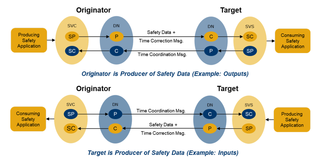
A multicast connection, as shown in Figure 7, allows up to 15 Safety Validator Servers to consume safety data from a Safety Validator Client. When the first Safety Validator Server establishes a connection with a Safety Validator Client, three link layer connections are established: one for data, one for time correction, and one for time coordination. Each new Safety Validator Server will use the existing data and time correction connection and establish a new time coordination connection with the Safety Validator Client.
Figure 7: Multi-cast Connection [Note: SP = safety producer, SC = safety consumer, P = producer, C = consumer]
Message Packet Sessions
CIP Safety has four message section types:
- Data section
- Time stamp section
- Time correction section
- Time coordination section
CIP Safety supports two different size ranges for the data section. The short data size, shown in Figure 8, provides high integrity transmission for up to 2 bytes of safety data. It includes an instance of the safety data, the time stamp and a 24-bit Safety CRC for the entire message; the 3 bytes of the Safety CRC are not contiguous.
Figure 8: Short Data, Extended Format

The long data size, shown in Figure 9, provides high integrity transmission for up to 250 bytes of safety data. In the long data size, the original safety data is sent along with a 16bit Safety CRC, an inverted copy of safety data, the time stamp and a 24-bit Safety CRC to cover the complemented data and time stamp. Like the short data section, the 3 bytes of the 24-bit Safety CRC are not contiguous.
Figure 9: Long Data, Extended Format

The time stamp section of the protocol is used to mark the production time of all safety productions.
The time correction section, shown in Figure 10, is used only for multicast messages. It is used to adjust for an individual consumer’s time count for multicast connections. This section is not needed in unicast messages because each producer is only associated with one consumer.
Figure 10: Time Correction for Multi-cast, Extended Format

The time coordination section, shown in Figure 11, contains the information sent from consumers to producers to correct the time value.
Figure 11: Time Coordination Message, Extended Format

The data section and time stamp section are combined into a single packet, while the time coordination section and time correction section are each sent in their own packet.
Connection Establishment
The EtherNet/IP network provides a connection establishment mechanism using a Forward_Open service, which allows producer to consumer connections to be established locally or across multiple links via intermediate routers. An extension of the Forward_Open, called the Safety_Open service has been created to allow the same multilink connections for safety.
There are two types of Safety_Open requests:
- Type 1: With configuration
- Type 2: Without configuration
With the Type 1 Safety_Open service, configuration and connections are established simultaneously. This allows rapid configuration of a device with simple and relatively small configuration data.
With the Type 2 Safety_Open service, the safety device must first be configured and the Safety_Open service then establishes a safety connection. This separation of configuration and connection establishment allows the configuration of devices with large and complex configuration data.
In both cases, the Safety_Open service establishes all underlying link layer connections across the local link as well as any intermediate links and routers.
Configuration
Before safety devices can be used in a safety system they must first be configured and connections must be established. The process of configuration requires configuration data from a configuration tool to be placed in a safety device. There are two possible sequences for configuration:
- Configuration tool connected directly to device or
- Via an intermediate device
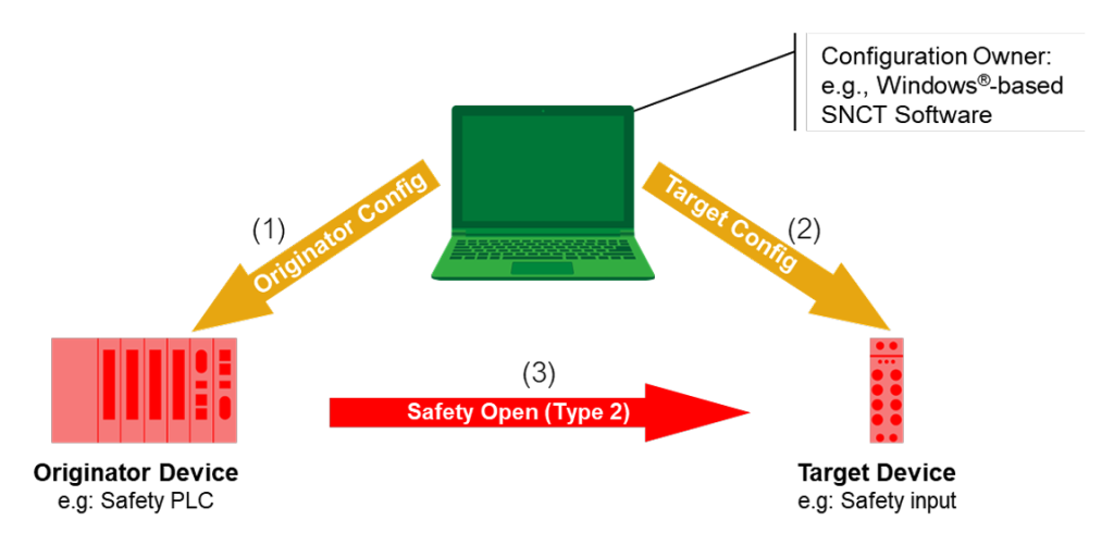
In the configuration tool to device case, as shown in Figure 12, the configuration tool writes directly to the devices to be configured (1)(2). The connection establishment must be a Type 2 Safety_Open (3).
Figure 12: Configuration tool directly to device [Note: SNCT = safety network configuration tool]
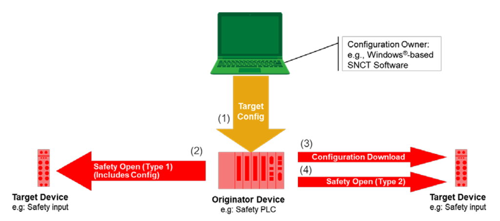
In the case of intermediate device configuration, as shown in Figure 13, the tool first writes to an originator (1). For modestly sized configurations, the Type 1 Safety_Open can be used to configure the device at the same time as the connection establishment (2). For very large configurations, a separate configuration download (3) and Type 2 Safety_Open can be used for connection establishment (4).
Figure 13: Configuration tool with intermediate device [Note: SNCT = safety network configuration tool]
Configuration Implementation
CIP Safety provides the following protection measures to help ensure the integrity of configuration:
- Safety network number (SNN)
- Password protection
- Configuration ownership
- Configuration locking
Safety Network Number (SNN)
The safety network number provides a unique network identifier for each network in the safety system. The safety network number combined with the local device address allows any device in the safety system to be uniquely addressed.
Password Protection
All safety devices support the use of an optional password. The password mechanism provides an additional protection measure, prohibiting the reconfiguration of a device without the correct password.
Configuration Ownership
The owner of a CIP Safety device can be specified and enforced. Each safety device can specify that its configuration is configured by a selected originator or that the configuration is only configured by a configuration tool.
Configuration Locking
Configuration locking provides the user with a mechanism to confirm that all devices have been verified and tested before being used in a safety application.
Safety Devices
The relationship of the objects within a safety device is shown in Figure 14. Note that CIP Safety extends the CIP object model with the addition of Safety I/O assemblies, Safety Validator and Safety Supervisor objects.
Figure 14: Safety Device Objects [Note: UCMM = unconnected message manager]

Safety Supervisor
The Safety Supervisor object provides a common configuration interface for safety devices. It centralizes and coordinates application object state behavior and related status information, exception status indications (alarms and warnings) and defines a behavior model, which is assumed by objects identified as belonging to safety devices.
Wireless
CIP Safety has been certified by TÜV Rheinland as a “black channel” protocol, which means that the safety integrity is not dependent on the physical media. As a black channel protocol, CIP Safety can be communicated with over different wired Ethernet platforms (10, 100 Mbps and 1 Gbps), fiber optics, and wireless systems such as WiFi (802.11a/b/g/n/ac). CIP Safety is expected to be forward compatible to standards like WiFi 6 (802.11ax) and 5G.
Summary
Communication networks have changed how today’s automation systems operate by distributing processing, sensors, and actuators to where they are needed. CIP Safety provides these same benefits to safety systems by providing scalable, routable network independent safety communication. Functions such as multicast messaging provide a strong foundation that enable users to create fast responding local cells that improve safety distances, while advanced functions such as multilink routing permit the seamless interconnection to remote cells to meet the expansion needs of the future.
Authors: David A. Vasko & Oliver C. Haya
CIP Safety: Safety Networking for Today and Beyond
(PUB00110R4)