


EtherNet/IP™ – CIP on Ethernet Technology
EtherNet/IP™ was introduced in 2001 and today is the most developed, proven and complete industrial Ethernet network solution available for manufacturing and process automation. EtherNet/IP is a member of a family of networks that implements the Common Industrial Protocol (CIP™) at its upper layers. CIP encompasses a comprehensive suite of messages and services for a variety of manufacturing and process automation applications, including control, safety, security, energy, synchronization, motion, configuration and information. As a truly media-independent protocol that is supported by hundreds of vendors around the world, CIP provides users with a unified communication architecture throughout the manufacturing enterprise.
With media independence comes the ability to choose the CIP Network best suited for each application. One of these possible choices is EtherNet/IP, which adapts CIP to Ethernet technology. Why adapt CIP to Ethernet? Ethernet, and TCP/IP– the Ethernet standard – is the same network technology used in the majority of local area net-work (LAN) and wide area network (WAN) architectures found in commercial applications around the world. These architectures connect computers and peripherals to one another, link business operations to the enterprise, provide users with access to web-based applications and encompass an installed base numbering in the billions of nodes. By leveraging the economies of scale in this proven commercial technology, EtherNet/IP provides users with the tools to deploy standard Ethernet technology for manufacturing and process applications, improving connectivity between people, partners and processes, devices, departments and systems in industrial applications, and opens up new opportunities for productivity, efficiency and flexibility.
EtherNet/IP offers several unique advantages for manufacturing and process automation applications:
- Complete producer-consumer services let you simultaneously and seamlessly control, configure and collect data from intelligent devices over a single network or use a single network as a backbone for multiple distributed CIP Networks.
- Compatible with standard Internet protocols — e.g., HTTP, FTP, SNMP, and DHCP — and standard industrial protocols for data access and exchange such as OPC UA.
- Compliance with IEEE Ethernet standards provides users with a choice of network interface speeds — e.g., 10, 100 Mbps, 1 Gbps and beyond — and a flexible network architecture compatible with commercially available Ethernet installation options including copper, fiber, fiber ring and wireless, and topologies including star, linear and ring.
- Compatible with the Ethernet-APL physical layer that enables long reach and hazardous area capable Ethernet for process field devices. Ethernet-APL is made up of the IEEE 802.3cg-2019 (10BASE-T1L), IEC 60079, and IEC 61158 standards.
- Parallel Redundancy Protocol (PRP) support, as defined in international standard IEC 62439-3, which provides high-availability for Ethernet networks. PRP technology creates seamless redundancy by sending duplicate frames to two independent network infrastructures.
- Options for industrially rated devices incorporating IP67-rated connectors (RJ45 or M12) with module and network status LEDs with device labeling for ease of use
- With the optional QuickConnect™ feature, minimization of power-up delays for applications where devices must connect and be ready to communicate with minimal delay (e.g., end of arm robotic tool changers)
- Support for functional safety with CIP Safety™ implemented in devices
- Synchronization of clocks across a system of interconnected devices using CIP Sync™
- Support of high-speed motion control applications with CIP Motion™
- Device level security with CIP Security™
- Energy usage monitoring and management via CIP Energy™
What is EtherNet/IP?
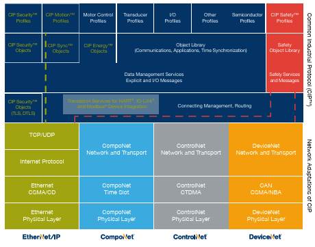
Figure 1: EtherNet/IP as Part of the CIP OSI Model
EtherNet/IP, like other CIP Networks, follows the Open Systems Interconnection (OSI) model, which defines a framework for implementing network protocols in seven layers: physical, data link, network, transport, session, presentation and application. Networks that follow this model define a complete suite of network functionality from the physical implementation through the application or user interface layer. As with all CIP Networks, EtherNet/IP implements CIP at the Session layer and above and adapts CIP to the specific EtherNet/IP technology at the Transport layer and below. This network architecture is shown in Figure 1.
Ethernet has the unique characteristic of being a network with an active infrastructure. Therefore, unlike typical industrial networks – which generally have a passive infrastructure that limits the number of devices that can be connected and the way they can be connected – the EtherNet/IP network infrastructure can accommodate a virtually unlimited number of point-to-point nodes, and with embedded switch technology, can also support linear and ring topologies providing users with unsurpassed flexibility in designing networks that accommodate their current requirements while enabling easy, cost-effective expansion in the future.
To further decrease complexity, EtherNet/IP provides a single point of connection for both configuration and control because EtherNet/IP supports both I/O (or implicit) messages: those that typically contain time-critical control data and explicit messages, and those in which the data field carries protocol information typical of client/server transactions used in configuration and data collection. As a producer-consumer network that supports multiple communication hierarchies and message prioritization, EtherNet/IP provides more efficient use of bandwidth than other device networks that use a strictly source-destination model. EtherNet/IP systems can be configured to operate either in a controller/device type of relationship or in a distributed control architecture using peer-to-peer communications.
The Physical Layer
EtherNet/IP uses standard IEEE 802.3 technology at the Physical and Data Link Layers. This standard provides a specification for physical media, defines a common frame format for moving packets of data between devices and supplies a set of rules for determining how network devices respond when two devices attempt to use a data channel simultaneously. This is known as CSMA/CD (Carrier Sense Multiple Access/Collision Detection).
As a network with an active infrastructure, EtherNet/IP is typically configured using a series of network segments constructed of point-to-point connections in a star configuration. The core of this network topology is an interconnection of Ethernet Layer 2 and Layer 3 switches that, as previously mentioned, can accommodate an unlimited number of point-to-point nodes. However, EtherNet/IP networks can also implement linear branching and single-fault tolerant ring topologies by utilizing embedded switch technology and Device Level Ring (DLR™) technology. These alternate topologies can be combined to optimize cable routing and machine communications layout. Most manufacturers offer pre-made or custom “patch” cables in a wide variety of lengths. Typically, a backbone of switches, in which each switch isolates a machine or a major part of a machine, are connected with high-speed copper or fiber optic cables. The other ports of the switch can be connected using twisted pair (e.g., CAT 5E, CAT 6) or fiber cables to the control devices for that part of the machine or manufacturing process. At a higher level, enterprise networks built on EtherNet/IP networks can make use of commercial technology to create architectures that range from complete separation to a fully converged plant-wide Ethernet.
Depending on their performance requirements, users can specify either Industrial EtherNet/IP products that have implemented options for the physical layer to improve reliability in industrial applications – such as high-noise applications or harsh environments with liquid and dust exposure requiring IP67 ratings – or Commercial Off-the-Shelf (COTS) products. In addition, CAT 5E or later Ethernet cable is recommended for reliability in manufacturing applications, as this cable provides greater noise immunity and other safeguards against harsh industrial environments. Both copper (shielded or unshielded twisted pair) and fiber cabling options are available, as well as sealed or non-sealed RJ45 connectors for copper wires and LT, SC, ST or MTRJ connectors for fiber optic cables.
The Data Link Layer
IEEE’s 802.3 specification is also the standard used for transmitting packets of data from device to device on the EtherNet/IP Data Link Layer. Ethernet employs a CSMA/CD media access mechanism that determines how networked devices share a common bus (i.e., cable), and how they detect and respond to data collisions.
Originally, Ethernet worked in a half-duplex mode of operation, meaning that a node could send or receive data, but it could not do both at the same time. This caused data traffic jams, which are unacceptable in time-critical control applications. Now, with full-duplex Ethernet (the de facto standard today), networked devices can both send and receive packets of Ethernet data at the same time. This, along with advancements in switching technology makes Ethernet suitable for use in the breadth of manufacturing or process applications.

The Media Access Control (MAC) protocol of the IEEE 802.3 specification is what actually allows devices to “talk” on the Ethernet network. Each device has a unique MAC address comprised of a 6-byte number that is regulated by IEEE and the product manufacturer to maintain uniqueness. This MAC address is used in the source address (SA) field of the frame to indicate what node sent the frame, and it is used in the destination address (DA) field to indicate the destination of the frame. Setting the first bit to a “1” in the DA field indicates a packet of data for multiple destinations, and enables an Ethernet node to transmit a single data packet to one or more destination nodes.
A single frame of industrial EtherNet/IP can contain up to 1,500 bytes of data, depending on the application requirements. The combination of real-time control with high-data capacity has made industrial Ethernet the network technology of choice, as more intelligence is embedded into smaller and lessexpensive devices. By utilizing standard Ethernet along with standard TCP/IP and UDP, EtherNet/IP is uniquely positioned to provide ease of configuration and operation, high data throughput, straightforward connectivity and provides the ability to merge the factory floor with the enterprise.
The Network and Transport Layers
At the Network and Transport Layers, EtherNet/IP utilizes standard TCP/IP (Transmission Control Protocol/Internet Protocol) to send messages between one or more devices. TCP/IP has been used in office applications for decades, and has wide familiarity and support. It provides the necessary communication protocol features needed to implement fully functional networks (i.e., an addressing scheme and mechanisms for establishing a connection with a device and exchanging data).
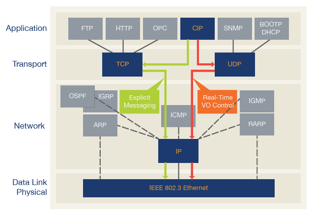
Figure 3: CIP – fully compatible with widely used Ethernet and Internet protocols
Also, at these layers, the standard CIP messages used by all CIP Networks are encapsulated. This TCP/IP encapsulation allows a node on the network to embed a CIP message inside an Ethernet message and send it to another node on the network, using the standard TCP/IP protocol.
By using standard TCP/IP and Ethernet, the lower layers of the TCP/IP stack and Ethernet interface chips (e.g., MAC controllers) will pass these messages through standard Ethernet infrastructure (e.g., managed or unmanaged switches, routers, etc.) to the destination node. TCP/ IP is used in EtherNet/IP to send CIP explicit messages, which are used to perform client-server type transactions between nodes. Some of these transactions will establish communications relationships that leverage UDP/IP, to exchange real-time data with other nodes on the factory floor. This is all seamless from the application perspective, which is made possible by utilizing standard Ethernet, TCP/ IP and UDP/IP communications.
The TCP/IP Suite consists of the following:
- The TCP portion of the TCP/IP protocol is a connection-oriented, point-to-point (unicast) transport mechanism that provides data flow control, fragmentation reassembly and message acknowledgements. Nodes will receive each message and acknowledge to the sender that it was received. If the message is fragmented across multiple frames, the sender will send the next fragment, which is acknowledged. This repeats until the entire message is received. At that time the receiving node will process the data and act accordingly. Since TCP is ideal for the reliable transmission of large and small quantities of data, EtherNet/IP uses TCP/IP to encapsulate CIP explicit messages, which are generally used to transmit configuration and diagnostic data, and also used to establish real-time (implicit) data transfers between devices.
- The IP portion of the TCP/IP protocol is the mechanism that assures packet routing through multiple possible paths. The ability to send messages to their destinations even when the primary path is disrupted is the basis of the Internet Protocol. Because EtherNet/IP uses standard IP, this same type of routing is used to maintain proper separation of factory floor control elements and other manufacturing systems through the use of standard infrastructure such as managed switches and Layer 3 routers.
For real-time data transfer, EtherNet/IP also employs UDP over IP to transport I/O messages that contain time-critical control data. UDP is a connectionless transfer mechanism that has low protocol overhead yielding smaller packet sizes and makes multicasting data to more than one destination possible. The smaller packets and multicasting support make the Producer/Consumer model possible with EtherNet/IP, and provide for streamlined data flow through the system, while the CIP Connection mechanism provides timeout mechanisms that can detect data delivery problems. For these reasons, UDP is well-suited to the task of transferring real-time implicit (i.e., I/O) data on EtherNet/IP.
EtherNet/IP uses two forms of messaging:
- Unconnected messaging is used in the connection establishment process and for infrequent, low-priority explicit messages. The unconnected resources in a device are referred to as the Unconnected Message Manager, or UCMM. Unconnected messages on EtherNet/IP utilize TCP/IP resources to move messages across Ethernet.
- Connected messaging on EtherNet/IP utilizes resources within each node that are dedicated in advance to a particular purpose, such as frequent explicit message transactions or real-time I/O data transfers. Connection resources are reserved and configured using communications services available via the UCMM.
The process of opening a connection is called Connection Origination, and the node that initiates the connection establishment request is called a Connection Originator, or just an Originator. Conversely, the node that responds to the establishment request is called a Connection Target, or a Target.
EtherNet/IP has two types of messaging connections:
- Explicit messaging connections are point-to-point relationships that are established to facilitate requestresponse transactions between two nodes. These connections are general purpose in nature and are typically used for frequent requests between the two nodes. They can be used to reach any networkaccessible items within a device. Explicit messaging connections utilize TCP/IP services to move messages across Ethernet.
- Implicit (I/O data) connections are established to move application-specific I/O data at regular intervals. These connections can be set up as one-to-one relationships or as one-to-many in order to take full advantage of the producer-consumer multicast model. Implicit messaging uses UDP/IP resources to make multicast data transfers over Ethernet a reality.
EtherNet/IP supports three device classes based on network communication capabilities: Messaging Class, Adapter Class and Scanner Class. Each class supports a basic set of communications services, but may provide other optional services too.
Messaging Class products support explicit messaging (connected or unconnected) that is sent to or received from all other classes of products. Messaging Class products are the targets of explicit message connection requests, and may also be originators of these requests, but they do not send or receive real-time I/O data.
Examples of products in this class include:
- Devices that perform configuration and programming of HMI products, robots and PLCs;
- Devices with applications that provide an operator interface to control systems (i.e., HMI products);
- Software applications that do not require real-time I/O response (e.g., MIS applications); and
- Network configuration and diagnostic tools.
Adapter Class products are the targets of real-time I/O data connection requests from Scanner Class products. They cannot send or receive real-time I/O data unless they are requested to do so by a scanner, and they do not store or originate the data communications parameters necessary to establish the connection. Adapter Class products receive explicit message requests (connected and/or unconnected) from all other classes of products. They may also exchange (peer) data using explicit messages with any class of device, but they typically cannot originate such relationships.
Examples of products in this class include:
- I/O devices such as I/O blocks or racks of I/O modules that produce and consume real-time I/O data;
- Weigh scales, welders, drives and robots that send and receive real-time data at the request of PLCs and other controllers;
- Weigh scales, welders, drives and robots that also receive explicit messages from control systems such as controllers and PLCs; and
- HMI products that send or receive explicit or real-time I/O data to/from PLCs or other controllers.
Scanner Class products are the originators of I/O data connection requests to Adapter Class products, as well as to other Scanner Class products that support Adapter Class functions (i.e., peer-to-peer explicit or I/O data). These products are typically also originators or targets of explicit connection requests to and from other classes of products, and they can also send or receive explicit messages to or from all other classes of products. Examples of products in this class include:
- PLCs, PC-based controls, other controllers and robots that send and receive real time data to and from I/O devices, PLCs, PC-based controls, drives, robots, weigh scales, welders and HMI products;
- PLCs, controllers and robots that send and receive explicit message data to and from other PLCs, robots, weigh scales, PC-based controls, welders and HMI products.
The Upper Layers
EtherNet/IP uses the Common Industrial Protocol (CIP), which is an object-oriented protocol, at the upper layers. Each CIP object has well-defined attributes (data), services (commands) and behaviors (reactions to events). CIP’s producer-consumer communication model provides more efficient use of network resources than a pure source-destination model by allowing the exchange of application information between a sending device (e.g., the producer) and many receiving devices (e.g., the consumers) without requiring data to be transmitted multiple times by a single source to each individual destination. In producer-consumer networks, a message is identified by its connection ID, not its destination address (as is the case with source-destination networks). In EtherNet/IP this is realized using the combination of the Connection ID and an IP Multicast group address. Thus, the producer-consumer model provides a clear advantage for users of CIP Networks by making efficient use of network resources in the following ways:
- If a node wants to receive data, it only needs to ask for it once to consume the data each time it is produced.
- If a second (third, fourth, etc.) node wants the same data, when it asks for it, the device will provide the multicast address and Connection ID of the message already being produced, so that all nodes will simultaneously receive a single message from the network.
CIP also includes “device types” for which there are Device Profiles. For a given device type, the Device Profile will specify the set of CIP objects that must be implemented, configuration options and I/O data formats. This consistency in object implementation for a given device type provides another clear advantage for users of CIP Networks by promoting a common application interface for a given device type and interoperability in networks comprised of devices from multiple vendors. For applications where unique functionality is required, it is also possible for an EtherNet/IP vendor to define additional vendor-specific objects in an EtherNet/IP-compliant product in order to support the functional requirements of particular applications that are unique to that vendor.
Seamless bridging and routing is perhaps the most significant advantage for users of CIP Networks for it is this mechanism that most protects the user’s investment for the future. The ability to originate a message on one CIP Network, such as EtherNet/IP, and then pass it to another CIP Network, such as DeviceNet®, with no presentation at the Application Layer, means that users can incorporate incremental application improvements to existing installations and/or integrate automation systems with diagnostic, prognostic and/or IT applications. Seamless bridging and routing between both homogeneous and heterogeneous CIP Networks is enabled by a set of CIP objects that defines CIP routing mechanisms (this is not the Internet Protocol routing discussed earlier) for a device to use when forwarding the contents of a message produced on one network port to another. This mechanism does not alter the contents of a message during the routing process. When using this mechanism, the user’s only responsibility is to describe the path that a given message must follow. CIP ensures that devices that act as gateways between the different CIP Networks handle the message correctly, independent of the CIP Networks involved.
Management of the EtherNet/IP Technology
EtherNet/IP is managed by ODVA, an international association of the world’s leading automation companies. ODVA’s EtherNet/IP management responsibilities include:
- Publishing The EtherNet/IP Specification;
- Overseeing the process to incorporate new enhancements to The EtherNet/IP Specification;
- Licensing the EtherNet/IP Technology to companies desiring to make and/or sell EtherNet/IP-compliant products;
- Promoting industry awareness of EtherNet/IP and its benefits; and
- Helping to ensure compliance of EtherNet/IP products with the specification through conformance testing and conformity reporting.
For more information about EtherNet/IP, CIP or ODVA, visit ODVA at www.odva.org.
About ODVA
ODVA is an international standards development and trade organization with members from the world’s leading automation suppliers. ODVA’s mission is to advance open, interoperable information and communication technologies for industrial automation. Its standards include the Common Industrial Protocol or “CIP™,” ODVA’s media independent network protocol – and industrial communication technologies including EtherNet/IP, DeviceNet and others. For interoperability of production systems and their integration with other systems, ODVA embraces the adoption of commercial-off-the-shelf, standard Internet and Ethernet technologies as a guiding principle. This principle is exemplified by EtherNet/IP – today’s leading industrial Ethernet network. Visit ODVA online at www.odva.org.
Technology Overview Series: EtherNet/IP (Pub 138R8)